Enhanced Weight on Bit Application in Hard Rock Drilling Through Innovative Anchoring Technology
Abstract:
An increasing number of geothermal projects require long horizontal well sections to be drilled through hard rock formations. Among these projects are those from well-known industry frontrunners that drill sets of inclined or horizontal wells to form downhole heat exchangers (closed loop Advanced Geothermal Systems – AGS) or Enhanced Geothermal Systems (EGS). These, and many other geothermal drilling scenarios, suffer from dysfunctions like insufficient transfer of weight on bit (WOB), drillstring buckling, and stick-slip that significantly impact cost and, ultimately, the feasibility of the project.
An innovative Downhole Anchoring and Drive (DAD) system will tackle the challenges associated with drilling long wells through hard rock and enhance especially those with long highly inclined sections. The DAD system grips the wellbore in close proximity to the drill bit and is designed to reduce damaging and inefficient drilling dysfunctions. The system includes smart control and actuation systems along with sensor feedback to autonomously drive the drilling process at the drill bit rather than at the surface. Moreover, it has the capability of applying significant axial push and pull forces to the drilling assembly and drillstring which enables additional WOB (essential for efficient drilling in hard rock) and dynamically optimizes it to dramatically improve drill bit and drill motor life and performance.
The first version of the tool was tested in Q2/2023 in a shallow test well of a leading rig contractor in Houston, TX. This paper summarizes the development and testing activities undertaken in 2024.

1. Introduction
The emerging concepts of AGS or EGS require drilling a significant quantity of long inclined or horizontal sections through challenging environments resulting from a combination of their high vertical depth (between 10,000 to 20,000 ft), hard crystalline rock formations with high friction factors (high drillstring torque and drag), and high formation temperature (a reliability challenge for downhole tools). The length of the horizontal section currently ranges from 5k (El-Sadi, 2024) to 9k ft (Longfield, 2022). The ability to drill long(er) horizontal sections cost effectively is essential for project economics (White, 2023). However, in practice, this is difficult to achieve because of the drilling dysfunctions that result when using conventional drilling technologies and processes in these applications.
The Downhole Anchoring and Drive (DAD) system currently under development will be a key component of future hard rock drilling systems and will eliminate and/or overcome the common drilling dysfunctions plaguing the cost-effective drilling of hard rock. It will reduce geothermal well construction costs through the application of significant and optimized downhole thrust force to the drill bit and allow faster and/or longer wells to be drilled than currently possible with today’s conventional technologies. What follows is an overview of the problems typically encountered while drilling hard rock, what the DAD system is, how it eliminates these, and ultimately how it is a key enabler to future Autonomous Reeled Drilling Systems (ARDS).
2. Challenges related to geothermal well construction
Challenges related to well construction of long horizontal sections include drilling dysfunctions which consume significant amounts of energy that could otherwise be used to drill rock faster. They take many forms but ultimately increase drilling cost and risk through elevated downhole tool wear and damage, reduced Rate of Penetration (ROP), increased number of trips in and out of the hole, and potentially, in the case of lost in-hole event, the loss of a well.
A typical example of dysfunction is torsional vibration – large fluctuations, usually periodic, in the drill-bit rotation rate despite a constant rotation rate at the surface. Torsional vibration ultimately stems from the inverse relationship between drilling torque and the rotation speed of the now ubiquitous PDC drill bit. This results in negative damping and a tendency for the drill bit’s rotary speed (and the drillstring connected to it) to oscillate when perturbed (Richard, 2007).
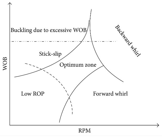
Another example of dynamic dysfunction is lateral vibration whereby the lateral stabilization of the drilling assembly and/or the engagement of the drill bit with the rock (a large component of drill bit lateral stability is the result of PDC cutter force balancing that relies on sufficient cutter engagement with the rock face) is insufficient to constrain lateral force instability or acceleration of the drill bit or other components within the drilling assembly. Not only can this form of dysfunction result in damage to downhole tools, but it can also cause significant irregularity in the wellbore path (tortuosity) that can then result in poor weight transfer to the drill bit (and further lateral vibration issues) as drilling progresses (Dupriest, 2013). Two common types of lateral vibration are forward whirl – typically occurs with limber drillpipe/collars that process in the same direction and similar frequency to drillstring rotation – and backward whirl – typically occurs on the drill bit and stabilizers whereby the rotation of the component within the wellbore is in the opposite direction to drillstring/bit rotation and at much higher frequency (Stroud, 2011). Both result in high-impact shock and vibration damage along with rapid accumulation of bending fatigue (especially in the case of backward whirl).
Dynamic stability plots show the relationship of the above dysfunctions to drilling parameters (Figure 1). For maximum performance, it’s desirable to work toward the upper right of the stability plot using the highest WOB along with the highest RPM while avoiding adverse dynamics – staying in the optimum zone. Watson (2013) confirmed through fundamental cutter testing that PDC drill bit ROP and life are maximized in hard rock by drilling at high WOBs.
Avoidance and/or mitigation of dysfunction is challenging. Typically, the cause of the dysfunction is at the bottom end of the drilling assembly (for instance, the PDC drill bit) whereas the control and actuation system is many kilometers away on the top side. This results in a severely underactuated drilling system that can be very challenging to control (Krstic, 2022 & Auriol, 2022).
Figure 2 shows a drillstring drag analysis for the longest 3D granite well drilled in Thailand (Thai, 2022). This well reached a Total Depth (TD) of 22,200 ft (6768 m) with a circa 11,480 ft (3500 m) horizontal section. The cumulative drag at TD at 0 rpm (sliding) was predicted at 185,200 lbs. with approximately 25 lb./m rate of increase in the horizontal section. The DAD system can apply up to 60,000 lbs. of extra WOB in this hole size. In this well, that would have resulted in an extra 2400m or 77% more horizontal footage before the same drillstring drag and levels of buckling would have been encountered.

What if the control and actuation system responsible for the drilling process were placed downhole in proximity (within 30m) of the source of instability e.g., the drill bit? What if it could apply significant and controlled downhole WOB to counteract the inverse bit torque to rotary speed relationship/negative damping and keep the drill bit cutters consistently engaged with the rock face to improve lateral stability and cutter life? What if this system could apply a significant WOB downhole directly to the drill bit to eliminate drillstring buckling and maximize reach? The answer is a more efficient drilling system that can drill both further and faster than the incumbent technology and ultimately reduces well construction cost and risk. This is what the DAD system offers the global drilling industry.
3. Downhole Anchoring and Drive (DAD) System
The DAD system is positioned within the bottom hole assembly (BHA) and contains hydraulically actuated gripping elements that anchor the BHA to the borehole wall and allow torsional and/or axial load to be reacted directly into the borehole rather than conveyed many thousands of feet above. The system contains a hydraulic thrusting unit that can apply significant and controlled thrust to the drill bit to both drill faster and actively reduce drilling dysfunction. The drilling process is controlled from the bottom of the hole with real-time sensor feedback to aid in optimization and includes many of the control modes that Drillers are accustomed to with the latest surface-based Automatic Drillers (ROP, WOB, Torque, etc.).
Dupriest and Noynaert (2022) showed that high WOB combined with more aggressive PDC cutters reduced drill bit wear rates and increased footage drilled in hard and abrasive formations. However, the same paper showed that this set-up generated stick-slip, an abrupt change in drill bit rotation rate, which had a very negative impact on the drill bit.
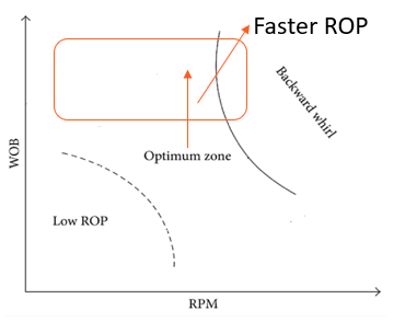
The resulting stability plot with the DAD system in the BHA can be seen in Figure 3. The threshold for buckling has shifted upward resulting from the ability of the DAD system to apply WOB
downhole and require less compression in the drillstring above (compression causes buckling). The stability resulting from local gripping of the wellbore has eliminated forward whirl and the ability to increase WOB and drill bit cutter engagement with the rock reduces the tendency to backward whirl. Ultimately, this extends the optimum zone, allowing higher WOBs and higher RPMs to be used, resulting in faster ROPs with fewer occurrences of damaging dynamics and adverse PDC cutter wear.
3.1 Testing of the Anchoring Functionality
The predecessor to the DAD system focused on mechanically isolating the drill bit from the ‘spring’ of the drillstring to provide a rigid torsional anchor point above the drill bit to react with the torque output from the drilling motor/drill bit and allows maximum weight to be applied without triggering stick-slip.
The Concept Prototype (CP) utilized hydraulic oil to energize gripper pistons. The gripper pistons extended to grip the wellbore wall and transmit torque. The tool comprised two anchoring units connected via a closed hydraulic circuit. This hydraulic circuit synchronized the movement of the two anchors such that while one was gripping the wellbore the other unit was resetting position to take over from the gripping unit when it reached the end of its travel. The target was to continuously react torque to the formation via the grippers up to the maximum ROP – 70ft/hr. for the CP.
The CP tool had no means of applying thrust to the drill bit and relied on it being applied by conventional means – heavy weight or drill collars in the BHA and the Driller controlling hook load/slack off weight to apply force to the drill bit. This CP was tested at the facility of a major drilling contractor in Houston, Texas, where they drilled a shallow cased hole filled with cement. The specifics of the test and results are described in Gajdos (2024). The shake-down test was successfully concluded with two main achievements:
- The CP tool reliably gripped the wellbore while drilling and the movement of the two anchoring units was sufficiently synchronized (via the closed hydraulic circuit connecting them) to ensure continuous gripping during the test. The CP achieved the required 70ft/hr. with testing not able to reach the maximum limit of the tool's capability.
- Downhole drilling dynamic subs located above and below the downhole motor detected vibrations reduced by up to 35% when compared to drilling without the CP in the drillstring.
Despite the successes, there were two notable challenges faced by the CP tool:
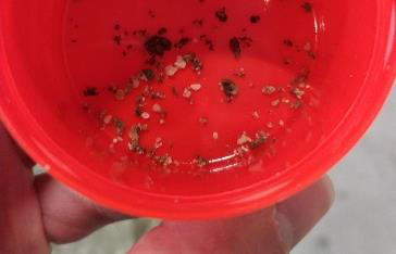
1. On the trip out of hole one, one of the hoses connecting the tool's hydraulic circuits to the surface hydraulic power pack – the CP tool relied on surface-based equipment for hydraulic power – was damaged. This damage allowed cement and casing debris to enter the tool's hydraulic circuits and this required a full disassembly of the tool to remove prior to rebuild. Additional filtration was placed on the hydraulic circuits to prevent the spread and migration of debris throughout the system, in the case of infiltration, although the commercial version of the tool was not envisaged to require hydraulic lines to be run between the tool and surface and hence this particular failure mechanism – debris ingress through damaged hydraulic hose – would not exist.
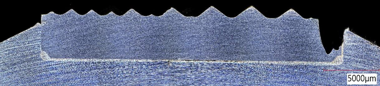
2. Figure 5 shows edge damage to the carbide gripping surface on the anchoring pistons. Minor surface damage was reported after interaction with hard rock. There is also the situation when the grippers interact with steel casing. The damage to the grippers after such a situation can be seen in Figure 5. Figure 5 shows edge damage to the carbide gripping surface on the anchoring pistons. Minor surface damage was reported after interaction with hard rock. There is also the situation when the grippers interact with steel casing. The damage to the grippers after such a situation can be seen in Figure 5.

The grippers were analyzed and several interesting conclusions were made:
- Most damage occurs on one side of the gripper. These are brittle fractures in the case of the carbide gripper element. Subsequent damage to the piston body from the carbide fragments can be seen as a scratch in the direction of rotation/forces acting on the gripper piston.
- The fractures were identified to be caused dominantly by tensile stresses because of one or more of the following: a) The carbide inserts do not conform to the inside of the casing/borehole – the edge stressed by tension fractured down to the brazed interface. b) Incomplete circumferential mechanical support of gripper pad in the gripper pistons – the braze filler sits sub-flush to the top surface of the counterbore in the piston. This results in poor load transfer from the gripper pad into the piston and results in increased tensile loading.
3.2 DAD Design and Configuration
A requirement for the original anchoring concept was for a purely hydro-mechanical tool with no electrical or electronic systems. This resulted from the desire for ultra-high temperature operations (350°C) for geothermal applications. As a drive to simplify the hydromechanical controls and modularize the design, it was decided to ‘electrify’ the anchoring tool with the addition of electronic actuation and control and, at the same time, add extra capabilities such as the application of controlled axial thrust/WOB to the drilling assembly and implementation of autonomous control loops similar to those in today´s cutting-edge automated drilling systems – these enhancements resulted in the DAD system as shown in Figure 7.

A summary of the enhancements of the DAD system over the CP tested at the drilling contractor’s facility in Houston:
- It incorporates an electronic/electrical control and actuation system to allow enhanced active control mechanisms to optimize the drilling process and reduce dysfunction.
- Allows the drillstring to be rotated through the anchors to minimize drillstring drag and allow the use of conventional directional drilling motors and processes (e.g., slide and rotate).
- Includes a comprehensive set of sensors and diagnostic data – e.g., pressure, torque, WOB, temperature, RPM, shock, and vibration.
- Utilizes pressurized drilling fluid to reduce tool complexity and cost and will follow a similar design ethos to the most commercially successful RSS tools.
- It includes an axial push/pull capability which can be used to apply additional WOB to improve ROP through higher depth of cut and/or reduced drillstring buckling/drag.
- The modular design allows multiple anchors and thrusting units to be stacked in series should higher forces be required.
- Utilizes a common electrical architecture that facilitates power and communications exchange between multiple modules and other third-party tools in the BHA creating the potential for a true integrated and autonomous drilling system.
The DAD System has two main tool configurations:
- Axial anchoring only – allows the central shaft to rotate through the anchoring modules and for true “plug and play” into conventional bent motors and jointed-pipe applications without the need for extra tools in the drillstring. The system utilizes modulation of axial thrust to mitigate stick-slip (and other dysfunctions).
- Axial and Torsional anchoring – Torsionally locks the central shaft running through the system to the anchors such that when the anchors engage the borehole wall the drillstring above the DAD system cannot be rotated. Drilling motor torque reacts into the borehole wall (via the anchors) rather than into the drillstring. Allows high torque and extended reach drilling with coil tubing.
The DAD system comes equipped with the following control modes:
- ROP Mode – This mode utilizes anchor traverse speed to control ROP, allowing for much more consistent drilling, eliminating common dysfunctions (e.g., axial stick-slip), and well control issues.
- Bit Torque Mode – Utilizes torque feedback to stabilize drilling torque, significantly improving motor and drill-bit life and allowing motors to be run closer to maximum power (faster ROP) without risk of damage.
- WOB Mode – This mode utilizes feedback from the WOB sensor to control axial thrust to stabilize WOB for a more consistent drilling process.
The commercial tool is undergoing development and testing for planned deployments towards the end of 2025.
4. Autonomous Reeled Drilling System (ARDS)
In addition to optimization of the drilling process through the proximity of the DAD system to the drill bit and its advanced control and actuation system, its ability to react torque and axial force into the formation is a critical enabler for drilling large diameter, hard rock wells with reeled pipe and/or coiled tubing. Coiled tubing is typically used for small diameter, low-cost well intervention and workover operations which require low torque and pull/weight capacity (compared to conventional jointed pipe in drilling applications). The ability to drill large hole diameter holes through hard rock with coiled tubing offers immense cost savings over conventional jointed pipe operations:
- Smaller, lower-cost drilling rig due to reduced derrick capacity and tubular handling requirements.
- Faster drilling and tripping times due to not needing to make/break rotary connections and pick-up/rack-back pipe (typically 3-4x the tripping speed compared to conventional jointed pipe).
- Improved well control through the ability to continuously circulate while tripping in/out of the hole.
- Reduced workplace hazards due to the elimination of rotary-shouldered connections made/broken on the rig floor.
- Improved command and control of the downhole tools through a continuous data link to the surface via wireline.
A schematic overview of the ARDS with the DAD system can be seen in Figure 8.
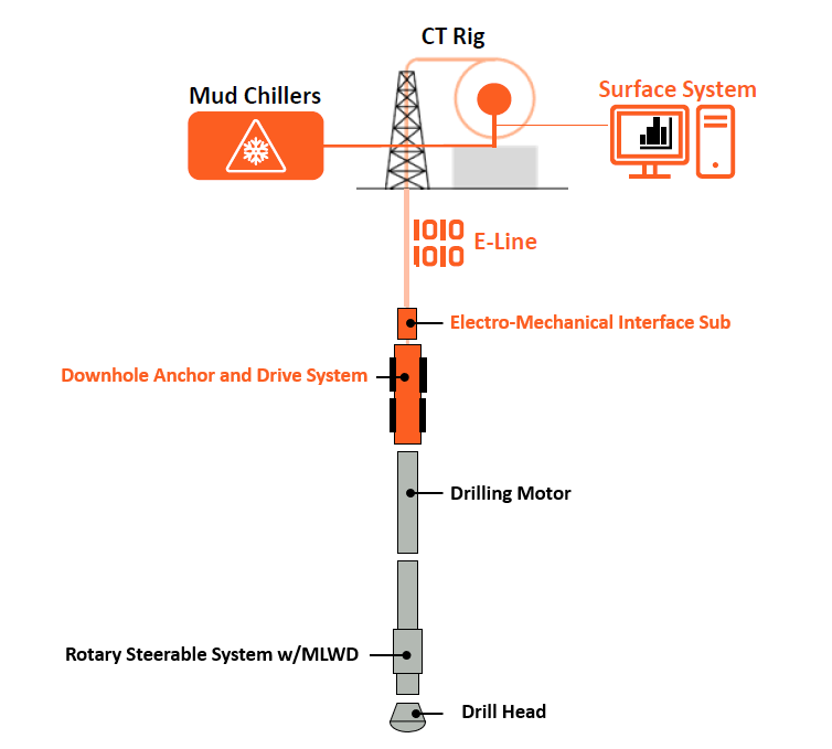
The components of the Autonomous Reeled Drilling System are as follows:
- Drill Head – conventional PDC, roller cone, or alternative rock destruction methods e.g., plasma.
- Directional Drilling Assembly – allows steering of wellbore along with navigational and petrophysical logging measurements. Pictured above with Rotary Steerable System (RSS).
- Drilling Motor – converts hydraulic energy in drilling fluid into mechanical energy for rotating the drilling assembly.
- DAD System – the anchoring system reacts to the drilling motor torque into the formation to avoid damage and twisting of the coiled tubing string. The 700 series DAD can react to the stall torque of the heaviest duty 7-in OD drilling motors (for drilling 8.5-in to 8.75-in nominal hole size).
- Coiled Tubing Interface – electromechanical connection of DAD system and BHA to coil tubing.
- Coiled Tubing – customized coil tubing with improved fatigue properties and mechanical/hydraulic capacities.
- E-Line – provides power and communications conduit between surface and downhole tools.
- Rig – standard CT/intervention rig.
- Surface System – this system allows data visualization, bidirectional communications, and control of the DAD system. It is also possible to receive MWD and LWD data.
5. Conclusion
This paper describes the innovative new Downhole Anchoring and Drive System proposed for hard rock drilling in geothermal applications. Typical forms of drilling dysfunction are discussed, along with the ability of the DAD system to mitigate these along with its ability to extend drilling distances through the application of downhole thrust. The DAD system will be commercially deployed in 2025 for geothermal applications. DAD system is also presented as the critical enabler of an Autonomous Reeled Drilling System, introducing a complete paradigm change in geothermal well construction.
References
Auriol, J., Boussaada, I., Shor, R., Mounier, Hugues., Niculescu, Silviu-Iulian., 2022. “Comparing Advanced Control Strategies to Eliminate Stick-Slip Oscillations in Drillstrings,” IEEE Access volume 10, pp. 10949-10969, 2022, doi: 10.1109/ACCESS.2022.3144644.
Dupriest, F. 2013, “Thus, The Lowly Stabilizer,” Presentation Given at International Association of Directional Drilling, July Meeting, 2013.
Dupriest, F. and Noynaert, S., 2022, “Drilling Practices and Workflows for Geothermal Operations,” Proceedings of the IADC/SPE International Drilling Conference and Exhibition, Galveston, Texas, USA. https://doi.org/10.2118/208798-MS
El-Sadi, K., Gierke, B., Howard, E., Gradl, C., 2024, “Review Of Drilling Performance in a Horizontal EGS Development,” Proceedings of the Stanford Geothermal Workshop 2024, Stanford University, USA.
Gajdos, M., Watson, G., Webb, M., Glover, D., Kristofic, T., Kocis, I., Lines, L., Murray, W., Codazzi, D. and Jeffryes, B., 2024, “Progress in Development and Testing of Anchoring Technology for Hard and Abrasive Drilling Conditions,” Proceedings of the Stanford Geothermal Workshop 2024, Stanford University, USA.
Krstic, M., 2022 “Control of Drill String and Flow Instabilities by PDE Backstepping” Proceedings of the Fifth International Colloquium on Nonlinear Dynamics and Control of Deep Drilling Systems, pp. 13-14, University of Maryland, USA.
Longfield, S., Schwarz, B., Hodder, M., Stuebing, T., Holmes, M., Vany, J., Mölk, D., 2022. “Eavor Loop™ Commercial Project at Geretsried, Molasse Basin, Germany,” Proceedings of the European Geothermal Congress 2022, Berlin, Germany.
Richard, T., Germay, C., Detournay, E., 2007, “A simplified model to explore the root cause of stick-slip vibrations in drilling systems with drag bits,” Journal of Sound and Vibration, Volume 305, Issue 3, 2007, Pages 432-456, ISSN 0022-460X, https://doi.org/10.1016/j.jsv.2007.04.015
Stroud, D. R., Lines, L. A., and D. J. Minett-Smith., 2011, “Analytical and Experimental Backward Whirl Simulations for Rotary Steerable Bottom Hole Assemblies.” Paper presented at the SPE/IADC Drilling Conference and Exhibition, Amsterdam, The Netherlands, March 2011. doi: https://doi.org/10.2118/140011-MS
Thai, L., Nguyen, N., Blackwell, G., and Minh D., 2022, “Longest 3D Horizontal Granitic Basement Section Record Drilled in Vietnam Using Friction Reduction Technology and RealTime Torque & Drag Management.” Paper presented at the IADC/SPE Asia Pacific Drilling Technology Conference and Exhibition, Bangkok, Thailand. doi: https://doi.org/10.2118/209915-MS
Watson. G., 2013, “Effect of Drilling Parameters on PDC Cutter Wear,” Hard Rock Drilling Workshop, International Research Institute of Stavanger (2013).
White, M., Martinez, M., Vasyliv, Y., Beckers, K., Bran-Anleu, G., Parisi, C., Balestra, P., Horne, R., Augustine, C., Pauley, L., Bettin, G., Marshall, T., 2023. “Closed-loop Geothermal Working Group Study – Understanding Thermal Performance and Economic Forecasts via Numerical Simulation,” Proceedings of the Stanford Geothermal Workshop 2023, Stanford University, USA.
Wu, S. X, Paez, L., Partin, U. Agnihotri, M., 2010, “Decoupling stick-slip and whirl to achieve breakthrough in drilling performance,” Proceedings of the IADC/SPE Drilling Conference and Exhibition, pp. 966–978, New Orleans, USA. https://doi.org/10.2118/128767-MS


