
Field Demonstration of Downhole Drive Units in Hard Crystalline Rock: Results from a Norwegian Test Well
ABSTRACT
Drilling efficiently in hard crystalline rock is one of the principal barriers to economically viabledeep geothermal energy. Among the dominant constraints are drilling dysfunction, in particulartorsional stick-slip, and the limited weight on bit that can be delivered and finely controlled througha long, compliant drillstring. The Downhole Drive Unit (DDU) system is being developed toaddress this challenge by gripping against the borehole wall and reacting weight on bit and torquedirectly into the formation, thereby delivering and controlling drilling loads at the bit independentof drillstring compliance. This paper reports the first field deployment of the system in a real hardrock wellbore, conducted across sequential field test phases at the NORCE Ullrigg test facility inStavanger, Norway during 2026. The programme progressed from validation of the core grippingand drive function in a single-unit configuration (Phase 1), through integrated dual-unit drilling ofhard crystalline rock (Phase 2), to control-system validation and performance benchmarking witha mud motor in the bottom hole assembly (Phase 3). The phase objectives spanned gripeffectiveness in irregular, oversize borehole geometry; generation of controlled downhole thrustat specification-consistent walking speed; continuous synchronized dual-unit operation; closedloop force control; and operation of a downhole turbine generator as a battery-independent powersource. The paper describes the test facility, well conditions, system configuration andspecifications, and the objectives and outcomes of each phase, and outlines the path towardcommercial deployment.
Keywords:
Downhole Drive Units, Downhole Gripping, Hard Rock Drilling, Geothermal, Field Trial,Drilling Dysfunction Mitigation, Coiled Tubing


Introduction
Drilling long, large-diameter wells in hard, hot crystalline rock remains one of the principal technical and economic barriers to next-generation geothermal energy. High formation temperatures, highly abrasive lithologies, and elevated unconfined compressive strengths combine Lines et al.to depress rate of penetration (ROP), accelerate tool wear, and drive frequent bit trips. The resulting non-productive time and tool consumption inflate well costs to the point where many deep geothermal prospects remain economically marginal (Gajdos et al., 2024).
A dominant contributor to poor performance in hard crystalline formations is drilling dysfunction, in particular stick-slip and low-frequency torsional oscillation. In these regimes the drill bit and lower bottom hole assembly (BHA) momentarily stall while the drillstring above continues to windup torsionally, then release as stored energy is discharged. The resulting cyclic acceleration imposes severe shock and vibration on the bit and downhole tools, limits the weight on bit (WOB)that can be safely applied, and reduces average ROP well below the smooth-drilling potential of the formation. Recent field work at Utah FORGE showed that high WOB combined with more aggressive PDC cutters can sharply increase ROP and footage per bit in granite, but also that doing so tends to provoke severe stick-slip that damages the bit (Dupriest and Noynaert, 2022); the ability to apply high WOB and the ability to control dysfunction must therefore advance together.Conventional mitigation relies on surface adjustment of WOB and rotary speed, but the long, compliant drillstring separating the surface controller from the bit introduces a transport delay that fundamentally limits how quickly dysfunction can be detected and corrected.
Considerable effort has been directed at the formation-facing elements of this problem.Geothermal wells historically relied on tough roller-cone bits for hard rock because early polycrystalline diamond compact (PDC) bits could not survive the heat and abrasion, though modern thermally stable PDC designs have since proven effective in hard geothermal rock. High temperature directional and steerable systems suitable for enhanced geothermal applications have also been developed. These advances improve performance at the rock face but do not address the underlying limitation in how drilling loads are delivered to, and controlled at, the bit through along drillstring.
Coiled tubing drilling (CTD), originally developed for small-diameter re-entry and slim-hole work, offers continuous circulation, fast tripping, and a reduced rig footprint, with reported penetration rates higher than conventional jointed-pipe rotary drilling in comparable conditions (Alagoz andTali, 2023). Recent work has demonstrated wired, instrumented coiled tubing tailored to shallow geothermal characterization (Torres et al., 2024). However, conventional coiled tubing cannot itself transmit the high WOB and torque required for large-diameter hard-rock drilling, and in deviated wells it is prone to helical buckling and lock-up. Whether the drillstring is jointed pipe or coiled tubing, the magnitude of WOB that reaches the bit, and the speed with which it can be modulated, are constrained by the compliance, weight, and friction of the string between surface and bit.
The Downhole Drive Unit (DDU) system is being developed to remove this constraint. By hydraulically gripping against the borehole wall and reacting WOB and torque directly into the formation, the system delivers and controls drilling loads at the bit itself, independent of drillstring compliance. GA Drilling has reported progressively on the development and testing of this downhole gripping approach for hard and abrasive formations (Gajdos et al., 2024). The conceptual design, laboratory performance testing, and first-year milestones of the broader autonomous CTD development programme, conducted in collaboration with a major national oil company, were described in a prior GRC publication (Lines et al., 2025). That work established the system's core performance targets and demonstrated, in laboratory testing, a downhole force ramp rate roughly an order of magnitude faster than an equivalent surface-based weight-on-bit Lines et al.controller. This paper reports the first field deployment of the DDU system in a real hard-rock wellbore, conducted across sequential field test phases at the NORCE Ullrigg Research and TestCentre in Stavanger, Norway during 2026, and describes the test facility, well conditions, system configuration and specifications, and the objectives and outcomes of each phase.
System Description
Downhole Drive Unit Principle
The system operates by hydraulically expanding drilling-fluid-energized gripping elements against the borehole wall, securing the tool body to the formation. Once secured, an internal hydraulic actuator applies axial thrust directly to the drilling assembly and drill bit, independent of drillstring weight. Because the grip transfers reaction loads into the rock rather than up the drillstring, the system can apply forces that far exceed what drillstring compression could deliver, particularly in highly deviated or extended-reach sections where helical buckling and drag limit the transmission of surface-applied WOB.
The DDUs are modular and stackable, so that available WOB and torque scale with the number of units deployed in the BHA. The system carries a comprehensive downhole sensor suite, measuring rate of penetration, bore and annulus pressure, thrust force, bit rotational speed via a precision angular rate gyro, drill-motor differential pressure and torque, and shock, vibration and stick-slip.These feed a control electronics package that can modulate WOB up to 100 times per second, operating closed-loop against downlinkable target values for thrust force, ROP, WOB, torque on bit, motor differential pressure, and stick-slip mitigation.
Tool activation and target downlinking use surface-controlled rotary speed and circulation pressure, requiring no additional wireline or telemetry infrastructure; uplink to a measurement while-drilling string is via a CANBUS connection. For sustained continuous drilling, two or moreDDUs operate in a coordinated handover sequence, one unit gripping and driving while the other resets, eliminating intermittent thrust and providing the stable, continuous force profile required for effective integration with an autodriller or closed-loop drilling controller.
The system supports two gripping modes. A combined torsional and axial gripping mode is used for hard-rock drilling with coiled tubing drillstrings, where the tool must also react drilling-motor torque into the formation. An axial-only gripping mode enables plug-and-play deployment with conventional jointed drillstrings, drilling motors, and directional processes. A more detailed description of the system architecture and laboratory validation results is provided in Lines et al.(2025).
System Specifications
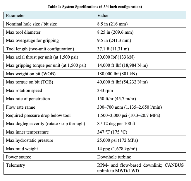
Key specifications for the 6-3/4” system, in a representative two-unit configuration, are summarized in Table 1. The 175°C temperature rating in combination with active cooling measures (mud chillers, insulated / coated drill pipes) enable drilling 250+°C bottomhole rock.Therefore, it is directly relevant to the demands of deep, hot, hard-rock geothermal wells.
Field Test BHA Configuration
For the Phase 2 (April 2026) field test, the BHA comprised the following elements from bit to surface: a hard-rock drill bit fitted with 16 mm chisel cutters; a pressure drop sub to generate the differential pressure required to drive the DDUs; spiral drill collars representing typical BHA stiffness; a float sub to prevent reverse circulation and debris ingress; additional spiral drill collars; the dual-unit DDU assembly; and drill pipe to surface. Because the field test used a conventional jointed drillstring, the tool was operated in its axial-only gripping mode (Section 2.1). Two power supply configurations were tested sequentially: lithium battery power in the first week and the downhole turbine generator in the second.
Test Facility and Well Conditions
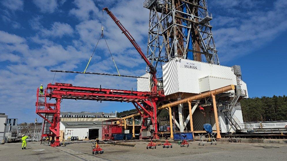
Field testing was conducted at the NORCE Ullrigg Research and Test Centre in Stavanger, Norway, shown in Figure 1. The facility is a purpose-built geotechnical and drilling test centre with full-scale rig infrastructure and instrumented test wells, enabling rigorous evaluation of downhole tools in actual crystalline rock formations without the logistical constraints of a commercial drilling campaign.
The test well is an 8.5-inch nominal diameter borehole drilled through hard Phyllite (UCS 22 ksi).For Phase 1, the well measured 968 ft (295 m) total depth, with steel casing set to 238 ft; when starting Phase 2, the open-hole section measured 1,093 ft (333 m). A key feature of the well was its deliberately challenging borehole geometry: large sections of the open-hole interval were significantly oversized, with caliper measurements indicating diameters of up to 10 inches, along with pronounced ovality and spiral geometry. These conditions provided a rigorous stress test for the gripping system.
Field Test Phase 1: Core Gripping and Drive Validation (February 2026)
Objectives
The objectives of Phase 1 were to validate the core gripping and drive concept in a real hard-rock wellbore, demonstrate grip effectiveness across irregular and oversize borehole geometry, generate and measure controlled axial thrust downhole, and achieve specification-consistent walking speeds in both cased and open hole environments.
Gripping and Thrusting Results
Phase 1 was conducted with two DDUs deployed sequentially. Figure 2 shows surface drilling data from Day 5, with standpipe pressure steps corresponding to increasing hydraulic drive pressure and the resulting hook load and rotation responses. Key results are summarized in Table 2.
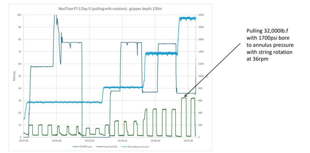
The 32,000 lbf annotation in Figure 2 denotes the axial force generated by the tool’s internal actuator while the grippers remained fully engaged against the borehole wall. The force output was measured against the stationary, gripped tool, while the drillstring was rotated at 36 rpm. This32,000 lbf is directly equivalent to the downward WOB the tool delivers while drilling, and the grippers react the full load into the formation throughout.
The 1,700 psi bore-to-annulus pressure annotation in Figure 2 is the differential pressure acrossthe tool between the tool bore — the inside of the drill pipe, through which drilling fluid is pumped— and the annulus outside the drillstring. This differential is the hydraulic input that energizesboth the grippers and the thrust actuator; the pressure drop across the tool is converted into grippingand axial force.
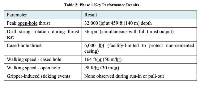
The peak open-hole thrust achieved (Table 2) directly validates the core value proposition: the ability to generate and sustain high downhole WOB in hard crystalline rock while the drillstring above continues to rotate. Maintaining drill string rotation during full thrust output confirms mechanical compatibility between the gripping and drilling functions within a single BHA, a requirement for integration with a downhole drilling motor.
The open-hole walking speed was intentionally limited below the specification target to manage hydraulic pressure risks in the oversized borehole interval; walking at the specification upper limit was demonstrated in cased hole, confirming that the limitation was operational rather than a system constraint. The absence of gripper-induced sticking events across borehole diameters up to 10inches is a significant operational result, demonstrating that the gripping design accommodates substantial borehole irregularity without increasing stuck-pipe risk.
Control System and Sensor Validation
Phase 1 validated several critical subsystem capabilities. Reliable on/off tool activation was confirmed using both rotary speed and circulation pressure as independent surface control triggers, requiring no wireline communication infrastructure. The proprietary Linear Position Sensor was validated for gripper position feedback downhole, providing real-time input to the closed-loop walking controller. Automatic closed-loop walking control was demonstrated successfully, with the tool autonomously maintaining target walking speed in response to downhole feedback.
Field Test Phase 2: Dual-Unit Integration and Hard Rock Drilling (April 2026)
Objectives
Building on Phase 1, Phase 2 targets were substantially more demanding: dual DDUs operating in synchronization within a single BHA.
Dual-Unit Integration and Drilling Performance
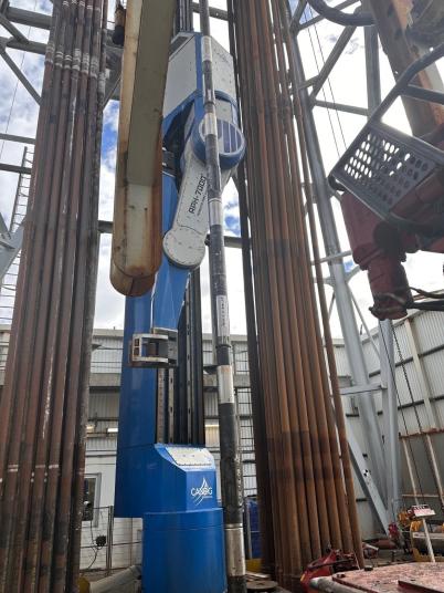
Figure 3 shows the BHA in the NORCE Ullrigg derrick prior to a drilling run.
During dual-unit operation, the two DDUs successfully executed multiple handover events per run. Figure 4 shows downhole data from a drilling run on 20 April 2026: the top panel shows the linear position of both units cycling in coordinated opposition, confirming the handover sequence, while downhole WOB tracks surface WOB during steady-state drilling and ROP holds a stable value across multiple handover cycles. A total of 66 ft (approximately 20 m) of hard Phyllite was drilled over 7.5 continuous hours of operation.
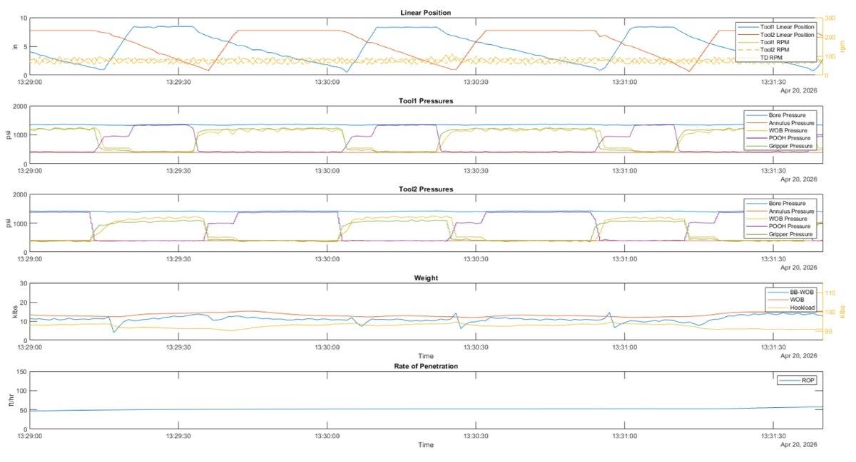
The dual-unit handover result is a fundamental technical milestone. Single-unit operation produces intermittent thrust: the tool drives for a stroke, then releases its grip and resets, temporarily removing downhole WOB. Dual-unit coordination eliminates this gap, providing a continuous force profile at the bit. This is the operating mode required for effective autodriller integration and for delivery of stable WOB that maximizes drilling motor efficiency and bit life in hard rock.
Force Control Precision
Surface closed-loop pressure control testing achieved ±35 psi stability at a driving pressure of 1,400 psi, equivalent to ±500 lbf force output precision, or approximately 1.5 to 2 percent of the nominal operating load. Figure 5 shows the test data, with bore and thrust pressures held tightly within the target band across the full test duration. This represents the best surface force-control result demonstrated at the time and enabled the closed-loop drilling modes — smooth WOB modulation for dysfunction mitigation, motor stall prevention, and autodriller integration — that were subsequently exercised downhole during Phase 3.

Turbine Generator
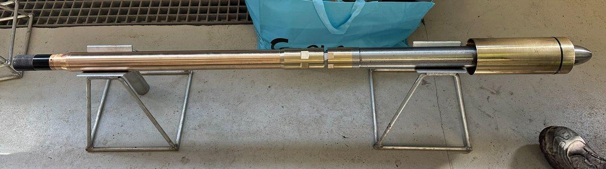
A downhole turbine generator prototype was developed in the first quarter of 2026 and is shown in Figure 6. It was successfully operated during the second week of Phase 2, confirming the turbine's ability to generate electrical power from drilling fluid flow and supply a representative operating load. By eliminating dependence on battery capacity, the turbine generator enables extended operational periods without tool retrieval for recharging, a critical enabler for deep geothermal drilling campaigns at 5,000 to 7,000 meters depth, where battery-limited windows would otherwise severely constrain continuous drilling.
Drilling Dysfunction Characterization
A dedicated rotary BHA run was conducted during Phase 2 to characterize the baseline drilling mechanics environment at NORCE. High-resolution downhole drilling mechanics data confirmed the presence of low-frequency torsional oscillation (LFTO) at approximately 1.5 Hz. Figure 7 shows the spectrogram: the dominant energy band persists as a horizontal stripe across multiple drilling intervals, with RPM varying sinusoidally from near-zero to approximately twice the average surface speed, consistent with a classic stick-slip pattern. High-frequency torsional oscillation and elevated lateral vibration were also recorded.
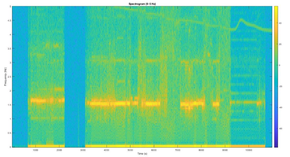
This confirms NORCE as a dysfunction-rich environment representative of hard geothermal rock and establishes the specific frequency signature against which the closed-loop control algorithms were calibrated for Phase 3. The measured fundamental lies well within the control bandwidth exercised during the Phase 3 campaign (Section 6).
Phase 2 Engineering Challenges and Development Priorities
Full achievement of Phase 2 targets was constrained primarily by the compressed turnaround between Phase 1 and Phase 2, which limited pre-deployment validation time, and by the inherent complexity of integrating two units for the first time in a live hard-rock wellbore. The main technical challenges were hydraulic sealing performance under combined pressure and rotation, sensor reliability under high shock and vibration, and control algorithm maturity for high-frequency thrust modulation. The aggressive hard-rock environment was deliberately chosen to push the tool to its limits and expose these failure modes early, under controlled conditions, rather than during commercial deployment. Hydraulic sealing architecture redesign, control algorithm development through flow-loop testing, and targeted electrical reliability hardening are underway ahead of Phase 3.
Field Test Phase 3: Control System Validation and Performance Benchmarking (June 2026)
Objectives
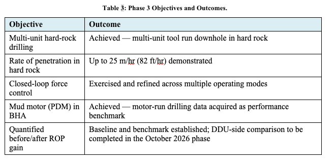
The primary objective of Phase 3 was to move from integration validation toward measurable performance improvement — increasing effective WOB delivery, improving ROP, and actively mitigating drilling dysfunction in hard rock — and it was the first deployment in which the DDU system operated with a mud motor (PDM) in the BHA. The methodology centred on a direct before-and-after comparison: a baseline rotary BHA run establishing reference ROP, WOB delivery efficiency, and dysfunction metrics, followed by an equivalent DDU run in the same formation interval. Phase 3 objectives and outcomes are summarized in Table 3.
Phase 3 Results
Phase 3 was run as a hard-rock validation of the DDU control system, deliberately operated at the edge of its operating envelope. Building on the thrust and rate-of-penetration performance established in Phase 2, the multi-unit tool was run downhole and achieved drilling rates of up to 25 m/hr (approximately 82 ft/hr) in hard rock. The closed-loop force control that differentiates the system was exercised and refined across multiple operating modes.
The campaign produced four concrete data assets. Dynamic thrust data were acquired across the operating envelope. Motor-run drilling data characterised the performance of the drilling motor and provide the benchmark against which subsequent performance drilling with the DDU system will be measured. A complete characterisation of the interaction between the hydraulics, the control system, and gripper performance was obtained. Finally, post-run analysis of the recovered units identified a set of reliability improvements.
Operating the control system at its limit surfaced a focused, well-characterised set of control and reliability refinements, captured in a prioritised plan of six focus areas to be closed ahead of the next campaign. The quantified before-and-after performance comparison is being completed in two stages: Phase 3 established the rotary and motor-run benchmark and validated the control system, while the equivalent DDU performance run — which quantifies the ROP and WOB-delivery gain against that baseline — is scheduled for the October 2026 campaign described below.
Path to Commercial Deployment
The next field campaign is scheduled for October 2026, running over two weeks. It forms the second half of the side-by-side benchmark, this time with the DDU system in the BHA, and is designed to quantify the performance gain relative to the Phase 3 baseline while continuing to prove the control system and its operating modes under load. Its principal targets are 1,500 ft of continuous drilling over approximately 25 hours with reliable, tuned multi-unit control. A further campaign is planned for the first quarter of 2027 with a launch partner, targeting endurance of 5,000 ft (approximately 1,500 m) over 50 hours as the step to commercial-pilot readiness on vertical wells.
Extended-Reach Deployment with an Industrial User in the Netherlands
Building on the NORCE field-test programme, the first commercial follow-on deployment of the DDU system is being prepared in the Netherlands, where GA Drilling, through a joint venture with Heatlinq, the Dutch geothermal project developer, will drill a geothermal well to supply heat to an industrial user in the Netherlands.
Energy Context and Rationale
The Netherlands is confronting severe electricity-grid congestion, with large parts of the network at or beyond capacity for new connections. The rapid build-out of intermittent renewable generation, principally solar and wind, has outpaced grid reinforcement and is not matched by dispatchable, controllable capacity able to supply firm energy on demand. Among the non-fossil options that can provide such dispatchable output at scale, the two most prominent are nuclear power and geothermal energy. For an industrial heat user, geothermal is especially attractive, since it can deliver continuous, weather-independent heat directly, displacing fossil-fuel combustion without adding load to a congested electrical grid.
For deep geothermal heat, three main technical routes exist. Conventional hydrothermal systems, which extract heat from permeable, water-bearing formations, are already in commercial use in the Netherlands, but they are limited to the low- and medium-temperature resources accessible at moderate depth and depend on the presence of a suitable natural aquifer. Enhanced geothermal systems (EGS), which engineer permeability in hot but tight rock, are difficult to apply in the Dutch setting: the great thickness of the sedimentary cover places the hot crystalline basement at considerable depth, and the high population density makes the induced-seismicity risk associated with hydraulic stimulation a serious constraint. Closed-loop systems, which circulate fluid through a sealed downhole loop and require neither reservoir permeability nor stimulation, avoid the seismicity and aquifer-dependence problems but are costly and hinge on a breakthrough in the economics of deep, hard-rock drilling. It is this drilling-cost barrier that the DDU system is designed to lower, and the deployment described in the following subsections applies the technology in a deep geothermal well developed for an industrial user in the Netherlands.
Project Context
The deep pilot exploration well is designed to reach more than 6 km measured depth assuming an approximately 3 km horizontal sidetrack with co-axial set-up including Vacuum Insulated Pipe (VIT). This is a substantial step change from the near-vertical NORCE test well: the Netherlands well introduces long drilling intervals, inclined and curved trajectory, and the extended-reach, high-friction conditions in which the ability to deliver weight on bit downhole — rather than through a long, compliant, high-drag drillstring — is most valuable.
Where the NORCE campaigns validated the core gripping-and-drive function, dual-unit integration, and the control system in a short, instrumented test well, the Netherlands well is designed to serve as a follow-on validating tool durability and operational procedures over extended drilling runs under realistic field conditions. The system is deployed on a conventional jointed drill-pipe string in its axial-only gripping mode (Section 2.1). The well will be drilled in stages. The surface and intermediate hole sections are drilled conventionally, without the DDU system, and the DDU system is deployed in the production section, where the extended-reach and inclined geometry make downhole thrust most beneficial.
Readiness and Performance Targets
Commercial and regulatory preparations are advanced. A memorandum of understanding with the industrial user has been signed and a firm contract is under negotiation; an exploration permit is in place, and a drilling permit application is in preparation, with submission expected in the third quarter of 2026. Memoranda of understanding have been signed with key delivery partners, and long-lead items are close to procurement.
Discussion
Progression Across Field Test Phases
The three field test phases represent a coherent and deliberate progression from concept validation to operational drilling demonstration. Phase 1 established that the core gripping and drive mechanism functions as designed in a real crystalline rock wellbore, producing the required thrust, tolerating borehole irregularity, and confirming specification-consistent walking speeds. Phase 2 advanced to integrated dual-unit drilling, demonstrating the handover mode fundamental to sustained hard-rock drilling and producing the first quantitative footage and operational duration data. Phase 3 validated the control system in hard rock at the edge of its operating envelope and established the performance benchmark; the quantified performance improvement against that baseline is being completed in the October 2026 campaign, the final step of the field qualification programme.
Relevance to Geothermal Drilling
The conditions at NORCE are representative of the formations targeted by Next-Generation Geothermal System. The system's ability to deliver high, finely controlled WOB directly at the bit addresses the two most significant drivers of poor drilling performance in crystalline formations: insufficient bit loading due to drillstring compliance and friction, and the inability to suppress torsional dysfunction quickly enough from surface. The turbine generator removes the battery-life constraint on run duration, enabling the long continuous drilling windows central to the factory-drilling economic model described in Lines et al. (2025).
Integration with the Autonomous CTD System
The current field test programme focuses on the DDU subsystem deployed in a conventional drill pipe BHA, in its axial-only gripping mode, enabling performance validation in isolation before integration with the full coiled tubing drillstring and surface equipment package described in Lines et al. (2025). For the integrated CTD system, the combined torsional and axial gripping mode will react drilling-motor torque into the formation, since coiled tubing cannot transmit reactive torque from surface. The demonstrated compatibility of gripping with simultaneous drill string rotation establishes the downhole performance baseline against which the integrated system will be validated in subsequent campaigns.
Conclusion
The sequential field test phases at the NORCE Ullrigg facility in Stavanger, Norway have demonstrated the core capabilities of the DDU system in hard crystalline rock under real operational conditions.
Phase 1 (February 2026) validated single-unit gripping and drive, generating 32,000 lbf of open-hole thrust with simultaneous 36 rpm drill string rotation, achieving walking speeds consistent with specification (up to 164 ft/hr in cased hole), and confirming no gripper-induced sticking across irregular borehole geometry up to 10 inches diameter. Autonomous closed-loop walking control and the Linear Position Sensor were validated downhole for the first time.
Phase 2 (April 2026) advanced to dual-unit integrated operation, drilling 66 ft (20 m) of hard Phyllite over 7.5 continuous hours with a stable ROP of approximately 50 ft/hr. Closed-loop force control of ±500 lbf was demonstrated at the surface, a downhole turbine generator was operated successfully for the first time, and low-frequency torsional oscillation at approximately 1.5 Hz was characterized, providing a validated dysfunction target for Phase 3.
Phase 3 (June 2026) validated the control system in hard rock at the edge of its operating envelope, confirming more than 30,000 lbf of thrust and rates of penetration up to 25 m/hr (82 ft/hr), acquiring motor-run benchmark data with a mud motor in the BHA, and identifying a prioritised set of six refinements ahead of the next campaign.
The quantified before-and-after performance gain against the rotary baseline is being completed in the October 2026 campaign, with a launch-partner endurance campaign planned for the first quarter of 2027. Together, these phases constitute the field validation programme required to underpin commercial deployment of the DDU system as a key enabling technology for cost-effective drilling of deep, hot, hard-rock geothermal wells.
In parallel, the first extended-reach deployment, with an industrial user in the Netherlands, is being prepared, with production-section drilling using the DDU system planned for 2027.
Acknowledgement
The authors acknowledge the support of the engineering and operations teams at GA Drilling, and the staff and management of NORCE Ullrigg for technical support throughout the field test programme.
REFERENCES
Alagoz, E. and Tali, B. "Applications and Limitations of Coiled Tubing Technology: A Glance." Science Journal of Energy Engineering 11 (2023), 10-18.
Dupriest, F. and Noynaert, S. "Drilling Practices and Workflows for Geothermal Operations." IADC/SPE International Drilling Conference and Exhibition, Galveston, TX, 10.2118/208798-MS (2022).
Gajdos, M., Kristofic, T., Kocis, I., Lines, L., and Murray, W. "Enhanced Weight on Bit Application in Hard Rock Drilling Through Innovative Anchoring Technology." Proceedings: Stanford Geothermal Workshop, Stanford, CA (2021).
Gajdos, M., Watson, G., Webb, M., Glover, D., Kristofic, T., Kocis, I., Lines, L., Murray, W., Codazzi, D. and Jeffryes, B. "Progress in Development and Testing of Anchoring Technology for Hard and Abrasive Drilling Conditions." Proceedings: Stanford Geothermal Workshop, Stanford, CA (2024).
Lines, L., Murray, W., Wisinger, J., Gajdos, M., Garcia, A., and Buck, N. "Autonomous Coiled Tubing Drilling System for Cost Effective Drilling of Large Diameter, Long Geothermal Wells in Hard, Hot Rock." GRC Transactions, Vol. 49 (2025).
Torres, C., Livescu, S., Carlisle, Z., Whyte, R., Gatabi, J., Clark, K. and Albaalbaki, B. "Geothermal Energy: A Novel Coiled Tubing Technology Transition." Proceedings: SPE/ICoTA Well Intervention Conference and Exhibition, 10.2118/218288-MS (2024).


