Progress in Development and Testing of Anchoring Technology for Hard and Abrasive Drilling Conditions
Abstract:
Over the last two decades there has been a significant advance in Polycrystalline Diamond Composites (PDC) bit technology, but PDC cutters still wear out when drilling hard and abrasive formations. Laboratory tests investigating Depth of Cut (DoC) of PDC cutters indicate that using low Revolutions Per Minute (RPM) but high DoC could significantly improve economics of drilling hard rock. However, Low RPM / High DoC is difficult to achieve in practice because of a damaging torsional vibration called Stick-Slip. If we can eliminate Stick-Slip and generally improve downhole stability, we will be able to apply more weight to a PDC drill bit and improve drilling economics.
The authors of this paper are involved in the development of plasma drilling technology. In parallel to this development, they invented a downhole anchoring system which can work not only with plasma drilling but also with conventional rotary drilling. Combining the anchoring technology with PDC bits and a downhole motor enables consistent drilling without stick slip, enabling longer lifetime of the drill bit and Bottom Hole Assembly (BHA) components. Using the anchor with High Torque / Low RPM downhole motors enables more rock to be drilled with the same bit, reducing the number of trips and the number of consumed drill bits.
Also, since the anchoring module is in contact with the formation, it provides a platform for direct measurements of different drilling parameters. The technology was for the first time tested in April/May 2023 at the testing site of leading drilling contractor in Houston, TX. The more advanced prototype is now under design with further testing expected throughout 2024 on a testing site in Norway.

1. Introduction
The most recognized geothermal projects in Europe (including those in Iceland and Tuscany, Italy) have been drilled predominantly with roller cone bits. These provide a stable, but relatively low Rate of Penetration (ROP), which often makes geothermal projects economically unfeasible. Therefore, there is a clear need to move to other drill bit types which could provide consistent and high ROP while maintaining competitive bit life.
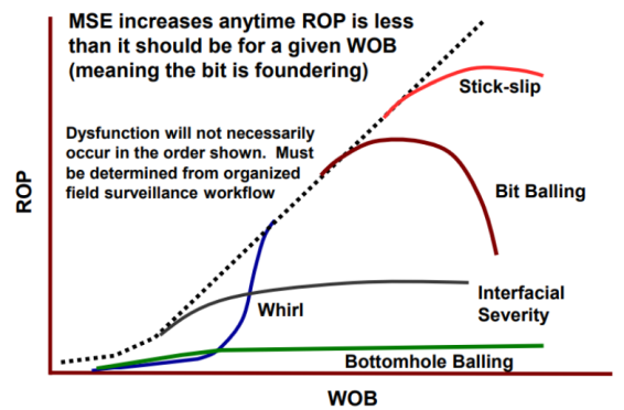
As was researched over the Utah FORGE 3-well program, instantaneous ROP with Polycrystalline Diamond Composites (PDC) bit was increased 400% and the record footage per bit 200% due to a couple of modifications including using double the Weight on Bit (WOB) and more aggressive drill bits (Dupriest and Noynaert, 2022). Among others, these modifications caused a multiplication of ROP in granite , which is one of the key rock types for future enhanced geothermal systems or super-hot rock projects. The problem with a more aggressive bit is that it often triggers a dysfunction called stick-slip. The rotation of the drill bit is not smooth, but periodically stops (sticks) and then breaks free (slips), with significant force and rapid accelerations. Figure 1 shows identification the presence of dysfunction with stick slip occurring in relation with high values of WOB.
Similar outcomes can also be taken from comparison of laboratory bench tests using PDC and Hybrid bits on another target geothermal formation – basalt. The PDC generated higher ROP than Hybrid bits, for a given set of parameters, but it was found to be laterally unstable at low WOB values (Savage et al., 2023).
Despite these promising studies, PDC bits remain limited in their performance in hard rock applications because the required Depth of Cut (DoC) is often difficult to achieve. Increasing the DoC requires increased WOB which may introduce many other drill string dysfunctions such as stick-slip, helical buckling, lateral instability and high-frequency torsional oscillations. These limit performance and the longer life and, in some cases, make things significantly worse. On the other hand, insufficient WOB can lead to other drilling dysfunctions, such as bit whirl and other modes of lateral vibrations, causing the bit’s cutting structure to fail prematurely (Moyes et al., 2023).
Therefore, downhole tools which enable the application of high WOB whilst eliminating the aforementioned limiters will be critical for the economics of advanced geothermal systems (Lowdon et al. 2023).
Granite, basalt and some other igneous rocks are attractive for super-hot geothermal energy production due to their ability to sustain high temperatures over long periods of time. This suitability is even more enhanced by their geological stability and durability (Khankishiyev and Salehi, 2023). The integrity of these formations minimizes the risk of well collapse and enables reliable use of a mechanism which can anchor the drilling assembly within the well using one or more gripping elements.
The authors of this paper have been in the development of plasma-based downhole tools. Within this development the team came up with the invention of an anchoring system for the proper positioning of the plasma tool downhole for well intervention applications (Kristofic et al., 2018) as well as for hard rock drilling (Gajdos et al., 2021). The concept of an anchoring system has been developed to extend the viability of conventional rotary drilling into harder formations and wells that are deep and have long lateral sections.
The presented anchoring system will extend the viability of conventional rotary drilling into harder formations by eliminating low frequency torsional vibrations, including Stick-Slip, and improving downhole stability. Consequently, it will enable driller to apply more weight to a PDC bit and improve drilling economics. (Brett, 1992).
2. Principles for use of anchoring system
2.1 Motivation for Development of Anchoring System
There are several pieces of evidence that indicate that temperature is critical to PDC life and high DoC in hard rock is beneficial.
A common observation in cutting tools, is that tool wear increases strongly as cutting speed increases. A direct result of increasing cutting speed is that the cutting tool gets hotter, with the cutting tip reaches several hundred degrees Celsius and is pushed to its chemical and mechanical limit (Freeman et al., 2012). Therefore, drilling systems and practices that keep the temperature of the cutting tip below these limits would significantly reduce wear and extend PDC bit life.
A common drilling practice is to “look after” a bit when drilling harder rock – for example applying a modest WOB so that the bit drills but at a comparatively low DoC and ROP. Experience shows that “looking after” a bit extends the time before it wears out. However, the analysis of some PDC durability tests indicate that this practice is likely to be harmful to the economics of drilling (Watson, 2013). A typical way of looking at Wear Tests is to compare Cutter Wear (Volume of PDC loss) with Time. Figure 2 shows the results of single cutter tests of the dry cutting of a granite. This can give the impression that low DoC is beneficial.

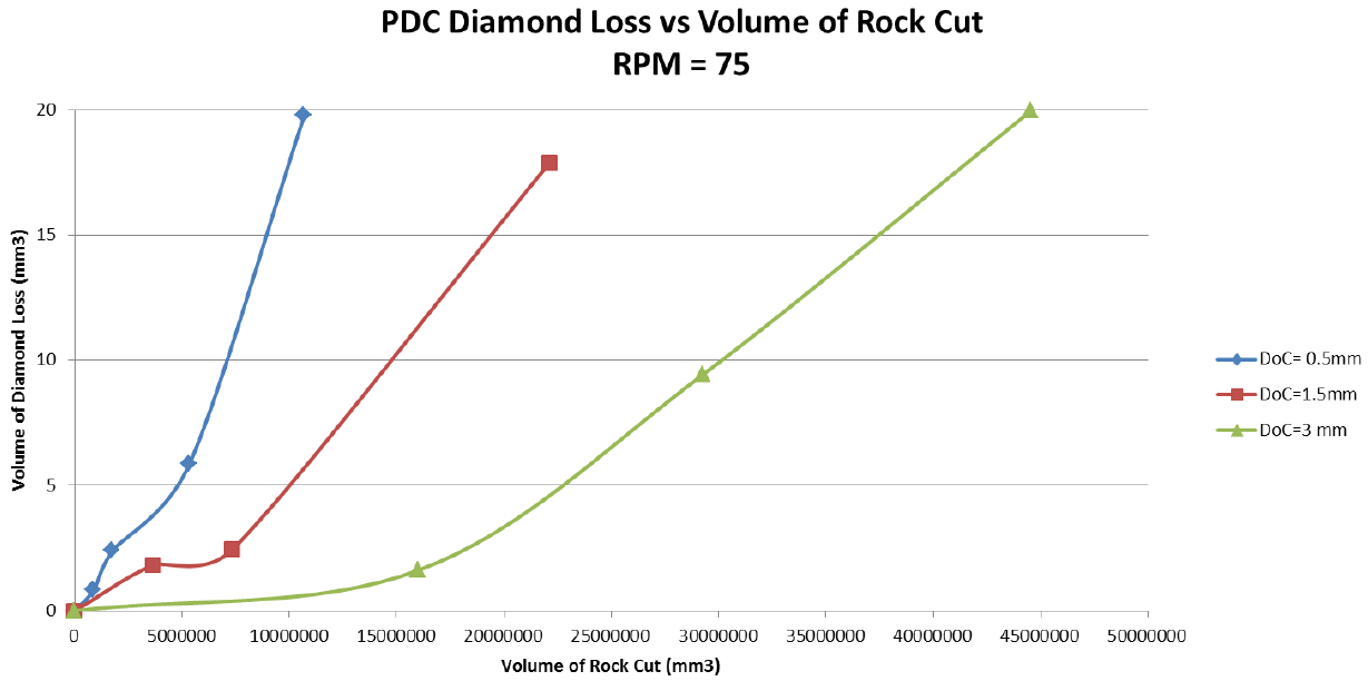
However, a different perspective is obtained when looking at the amount of Rock that has been removed during these tests. Figure 3 shows that significantly more rock was removed when using higher DoC than lower DoC. When comparing the three values of DoC, whilst the 0.5mm and 1.5mm DOC can last much longer than the 3mm test, the 3mm test removes much more rock before significant diamond loss.
Therefore, whilst increasing the DoC does reduce the time before the cutter wears out, the volume of rock removed before this happens is significantly higher. The effective life of the Cutter has been increased by increasing the DoC.
Therefore, beneficial operating parameters to extract more performance, and reduce drilling costs, when using PDC bit are:
- Use lower cutting speeds (RPM) to extend the life of the bit.
- Use higher Weight on Bit (WOB) to increase Depth of Cut to enable a bit to drill further.
The main barrier to applying Low Speed / High DoC drilling is damaging torsional vibrations, especially Stick-Slip which are more common when using low RPM and high WOB. In Stick-Slip the bit / Bottom Hole Assembly (BHA) stops at regular intervals causing the drill string to windup and the torque to increase. As the drill bit / drill string then breaks free, the bit and BHA accelerate rapidly, and the instantaneous RPM can easily be 2 or 3 times the average RPM at the surface. Stick-Slip is often accompanied by significant and damaging lateral vibration of the bit or BHA during the high speed "slip" phase.
Unlike many types of vibration, Stick-Slip can be self-sustaining due to (1) the difference between the static and dynamic friction between the drill string and well-bore and (2) the inverse relationship between RPM and bit torque. Once Stick-Slip has started it can be difficult to stop without stopping drilling and letting the vibrations dissipate.
The prevalence of Stick-Slip increases with higher DoC and longer drill strings because:
- The predominant cutting action of PDC bits is by shearing the rock. This requires significant levels of torque to be applied to the bit. Higher depths of cut and harder rocks require more torque, resulting in more stored energy in the drill string.
- The drilling torque is transmitted along the entire length of the drill string. The drill strings in deep and extended wells are frequently several miles / kilometers long and have significant axial and rotational flexibility. This system is very susceptible to large scale torsional vibrations.
The actual twisting and storing of energy during Stick-Slip takes place in the drill string. There are components that can be used in the drill string to reduce the risk of Stick Slip, such as:
- Use a heavier BHA to increase its inertia.
- Run roller reamers or non-rotating stabilizers.
- Use smooth edged stabilizers with spiral blades.
- Use a near bit stabilizer.
- Use roller cone bits.
- Use more heavy weight drill pipe to increase inertia.
- Use an anti-Stick Slip string tool.
Anti Stick Slip tools are available, such as those designed to reduce the risk of Stick-Slip starting. However, they do not address the fact that the most significant component of Stick Slip is the drill string and that a fundamental cause is the high levels of torque in the long and flexible torsional spring. The concept of the anchoring system is to completely remove the drilling torque from the drill string.
2.2 Wells Suitable for Use of Anchoring System
Any anchoring system with the aim to reliably grip the wellbore would work mainly in hard and stable formations. This would prevent any damage of the wellbore wall. Another perspective is that the system would be useful mainly in applications where stick-slip or weight transfer issues are expected. Therefore, a simple classification of wells was developed to show where the added value of the anchoring system is most likely. Figure 4 represents this classification.
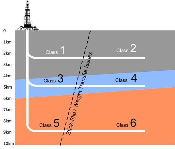
These six classes can be expanded by also applying a parameter for hard rock (as H). Table 1 shows proposed components of BHA for well classification shown in Figure 4. These cases highlight the use of an Anchor not only with drill pipes but also using coiled tubing or transfer line which can be advantageous for deep applications using plasma drilling. In these cases, an electrical conduit is integrated into the drill string to deliver a sufficient power downhole.
Table 1 Proposed components of BHA for well classification shown in Figure 4; “H” well type signifies UCS>25kpsi, typically igneous or metamorphic rocks; SS-PDM = Selectable Bend Motor; SS-PDM-metal = Selectable Bend Motor with metal-to-metal power section.


From this table it is obvious that an anchoring system is useful mainly for 2H, 3 and 3H for the basic anchoring functionality. For classes of the wells with higher measured depth (4-6H) it would be essential to also have ability to increase WOB on bottomhole. Additionally, for wells with higher TVD it would be beneficial to use a high temperature version of the system.
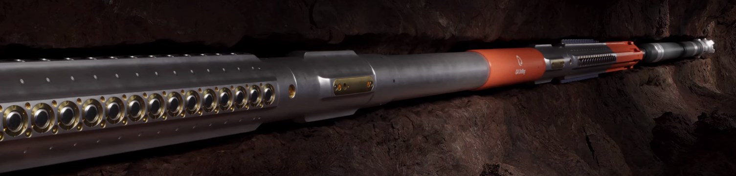
An example of BHA components based on the table for well class 3 or 3H is shown in the Figure 5. It includes a Metal to Metal downhole motor which are more sensitive to the lateral vibrations than motors with elastomers. The reason is that even moderate vibrations may damage clearances between the rotor and stator. Therefore, an anchoring system is enabling technology for Metal to Metal downhole motors in applications where Stick Slip occurs often.
2.3 Design of anchoring system
The anchoring system is a new downhole tool and designed to be used in the Bottom Hole Assembly, above a conventional downhole motor at the end of the drill string. The system fully grips the wellbore, transferring all the drilling torque directly into the wellbore and therefore removing the torque from the drill string. While drilling, the drill string is prevented from rotating but is allowed to slide down through the tool. The driller applies the WOB from the surface using the draw-works and drilling brake in the conventional way.
The system comprises two Gripper Sections and a “Walking System”. The power comes from a downhole power unit.
2.3.1 Gripper Section A requirement of the tool is that it fully grips the wellbore and so creates a torsional anchoring effect. Thus, a critical aspect is the effectiveness of the Gripper Sections. The current design is the result of significant testing – using pads of different materials, sizes, shapes and methods of manufacture. The results were assessed not only for effectiveness but also consistency and repeatability.
The effective friction from these tests became an input into the design decisions for number of grippers and the requirements for the internal hydraulic system activating the grippers. The design is a balance between the conflicting effects of the number of grippers, size of tool and system pressures. The aim was to create a consistent and reliable tool.
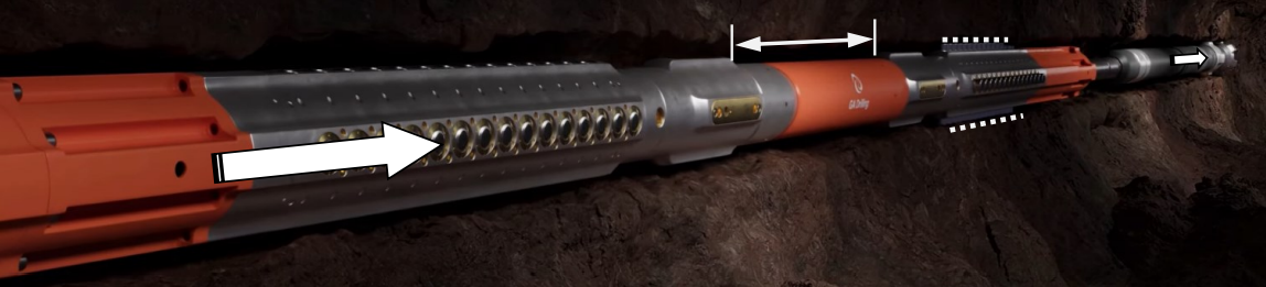
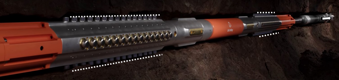
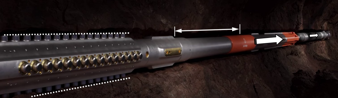
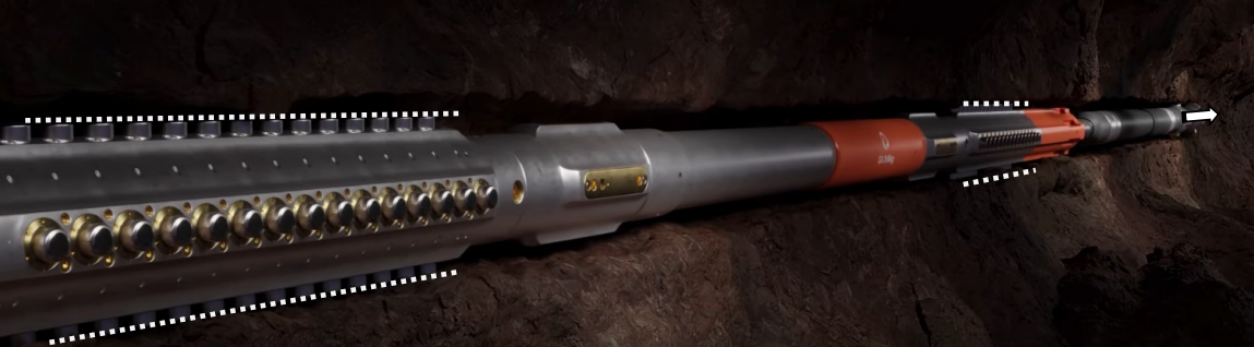
2.3.2 Walking System An early design strategy was to make the system effectively “invisible” to the driller while drilling. After the Anchor is switched on, it “walks“ down the hole as the bit drills. This is achieved by having two Gripper Sections that grip alternately, with one Gripper Section gripping as the other is pushed downhole by the Walking System at over twice the ROP of the bit. As the second Anchor reaches the end of a “step”, it is in the correct position to be activated. The first Gripper Section is then released and pushed downhole.
The Walking System manages the walking action of the Gripper Sections. It also ensures that the torque is continuously transferred into the wellbore by having a brief “hand-over” period. During this hand-over, an activated Gripper is not released until the other Gripper is activated and engages with the wellbore. Importantly, the drill string is free to continue through the system during this hand-over, thus also maintaining a continuous drilling action.
2.4 Operation of anchoring system
The tool walks downhole as the Gripper Sections go through a coordinated series of actions (Grip, Release, Move, Grip, Release, Move, etc.). The movement is explained with the white arrows in the Figure 6 below.

To enable rotation of the drill string above the anchoring system (for example for the purpose of reliable cuttings circulation), there could be a swivel located above the anchoring system with a lock/unlock function to facilitate orientation of the BHA for directional drilling.
Since the anchoring system can be engaged with the formation throughout the whole drilling duration, it stabilizes the drill string not only laterally, but can generate axial thrust causing an increase of WOB. This can be an important feature for innovative geothermal concepts which are currently under demonstration and include drilling of long horizontal sections in hard rock conditions (namely closed loop drilled heat exchanger and Enhanced Geothermal Systems with long sequentially fractured horizontal laterals). Without an anchoring system, these wells may suffer from various drilling dysfunctions caused by insufficient WOB transfer.
3. Results of field testing of anchoring system
A full-scale prototype of the Gripper Sections, Walking System and Hydraulic Switching unit were tested at two shallow well testing facilities in Bratislava, Slovakia and Houston, TX.
3.1 Testing in Bratislava, Slovakia
Design of the tool and its preparation for field testing was based on a series of various tests including:
- Friction testing of grippers applied on rock samples.
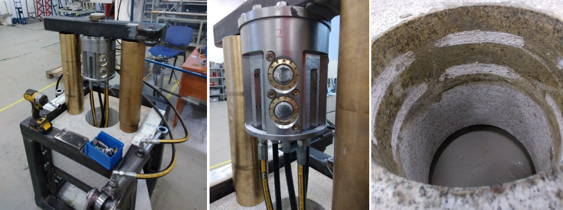
- Scaled Prototype Test (Figure 7)
- Rebound Test of Walking System.
- Side load test.
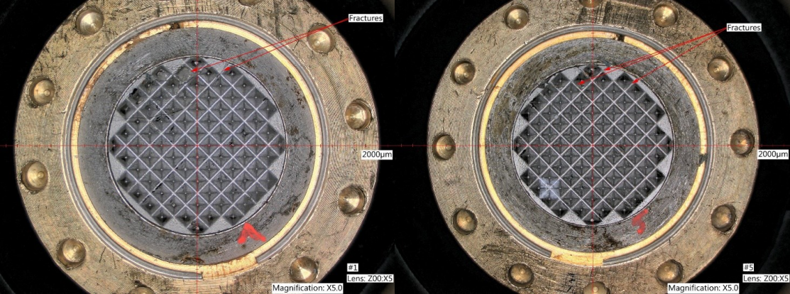
- Keyway and Grippers Durability Test (Figure 8)
Later, the prototype of the anchoring system was tested at a private testing facility near Bratislava, Slovakia that has vertical 9 7/8” casing cemented below ground. The Anchor was run inside the casing, gripping the casing wall, up to 100 ft/hr (31 m/hr). The initial tests, presented below, were run without any applied torque. Another phase of testing is to run at inclinations up to horizontal and increasing levels of torque.
The system was assembled with position, pressure, and temperature sensors to evaluate the behavior of the tool. As shown below, the action of the tool was consistent across the full range of ROPs. The action of the tool is illustrated in Figure 9 as the prototype going through several walking steps.
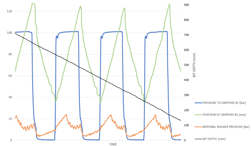
The black diagonal line shows the steady downward motion of the tool while:
- The actuating pressure to a Gripper Section is switched On and Off (Blue “square” wave),
- The Gripper Section moves up and down within the tool (Green “saw-tooth” trace),
- The internal pressure of the hydro-mechanical Walking System varies through the phases of walking and hand-over (Orange trace)
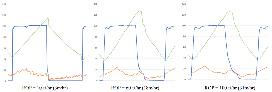
The speed of the walking is not determined by the anchoring system but is a response to the speed of the drill string through the system. The current design has been tested up to 100 ft/hr (31 m/hr). The pattern of behavior was very consistent across different ROPs, as illustrated in Figure 10, comparing the measurements from 10 to 100 ft/hr (3 to 31 m/hr).
3.2 Testing in Houston, TX
In April and May 2023, the prototype of the anchoring system was tested at a rig site of a leading drilling contractor in Houston, TX. The test was conducted in a shallow test well filled with cement having 8,000 psi compressive strength to simulate the conditions of hard rock. The target was to drill approx. 30 ft of cement. The test confirmed the system´s ability to reliably walk and grip while drilling. Since at the time of the test the power and hydraulic module were not fully developed, the test was executed with these modules located on the rig floor. Photos from the demo day for industry experts held on April 25th are shown in Figure 11.

The second objective of the test was to prove that the system minimizes vibrations caused by drilling. For this purpose, we used 6.75” Drilling Monitoring System (DMS) view units, which measured g values in three axes. For lateral vibrations analysis, we have chosen X and Y axes data from April 17 when we were drilling a pilot hole (Figure 12, left) without the anchoring system. These were compared with data from April 25 when we were drilling with the anchoring system during a demonstration day for industry experts (Figure 12, right).

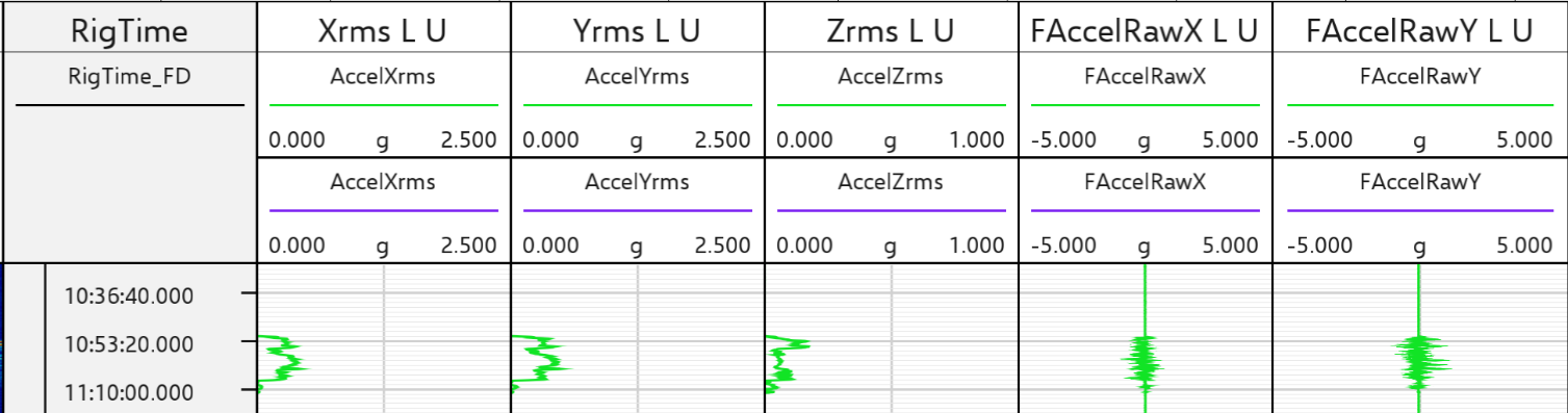
Sample of the analyzed data from 6.75” DMS units located below the downhole motor when drilling using the anchoring system is shown in Figure 13.
The results shown in the table below indicate that anchoring system reduced lateral vibrations by 8 to 35% when compared to drilling without it. Since low-frequency oscillations are increasing with the depth of drilling, we expect further benefits of anchoring system with drilled depth.

Based on the achieved test results, the anchoring system has a potential to significantly improve drilling efficiency of geothermal wells in hard crystalline formations and wells with long inclined or horizontal laterals.
After the test, the team focused predominantly on designing the power and hydraulic module and its integration into bottom hole geometry. The testing matrix continues with testing in granite formations on a test rig near Stavanger, Norway in Q1/2024.
4. Future development pathways
Another opportunity for increasing drilling efficiency is to install sensors into the anchoring system to provide drilling related measurements currently available from various commercial MWD and LWD systems, for instance drill pipe and annular pressures, weight on bit and motor torque. The following parameters are under consideration:
4.1 Downhole measurement of ROP
Currently ROP is measured at the surface. Partly because of the interactions between drill string compliance, hook load changes and uncertainty in string friction induced distortion of the stress distribution along the drill string, the rate at which the drill string enters the hole is an inherently imprecise indicator of the bit’s rate of penetration.
Anchoring system gives the opportunity to get a true downhole ROP measurement. The gripper unit which engages the borehole wall provides a fixed point of reference. A displacement sensor measuring the separation of the fixed and moving gripper units could be differentiated to give a measurement of the rate of penetration of the components below it. This measurement should have a precision which is not achievable with any current ROP measurement. It is possible to measure the ROP simply as time measured between walking steps if this is precise enough.
4.2 Downhole measurement of WOB
Weight on bit (WOB) and torque has historically been attempted with stain gauges mounted on collars and, in the presence of a motor, people used motor pressure drop to infer bit torque. Strain gauges measurements have shown poor accuracy because the measured strain depends more on pressure and temperature than torque and weight.
With anchoring systems, adequate instrumentation of the keys balancing the bit torque would provide an accurate torque measurement and pressure measurement on the walker directly leading to WOB. Unlike incumbent systems, these would be unprecedented measurements enabled by the fixed geo-referenced points created by the grippers.
4.3 Downhole measurement of some other parameters
Mechanical properties such as formation strength, anisotropy, Young’s modulus are currently inferred from sonic logs. Sonic logs provide a formation’s interval transit time, which is a measure of how fast elastic seismic compressional and shear waves travel through the formations.
However, an anchoring system would allow direct measurements instead of interpretations. Attached to the grippers themselves is a suitable location for a survey package (requiring non-magnetic components) as it sits firmly in one place for a long time, thus enabling a measurement of high accuracy compared to sensors subjected to shocks and vibrations as in conventional MWD.
- In situ Formation strength, representing pressure that the formation can withstand, can be measured directly from the pressure acting on the gripper’s piston as they engage in the borehole wall.
- Anisotropy of in situ formation strength, from a variation of the above around the wellbore. This is key to map out formation principal stress directions, key to the validation / calibration of mechanical earth models (MEM). This is particularly critical in areas with high tectonic activity, which tends to often be the case in geothermal projects.
- Instrumenting the gripper’s pistons displacement will give the rock deformation leading to an indication of strain which when combined with the stress will give Young’s modulus.
- The possibility of having at least one or two pistons fitted with a smaller end tip to increase the contact pressure with the rock thus extending the measurement dynamic range.
- Gripper extensions give a quadrant caliper (potentially multi-pass, since both grippers will go past the same section).
5. Conclusion
The paper summarizes some of the challenges when drilling hard and abrasive formations in geothermal applications and that laboratory indicate that using PDC bits at low Revolutions Per Minute (RPM) but high DoC could significantly improve economics of drilling hard rock.
It proposes a method for drill string stabilization by a downhole torsional anchoring system. Its prototype has been tested in 2023 on test rigs of leading drilling contractors in Bratislava, Slovakia and Houston, TX. The tests confirmed the system´s ability to reliably walk and grip while drilling up to 100 ft/hr (31 m/hr). It also indicates that the system may reduce vibrations caused by drilling.
Based on theoretical study and achieved results, the anchoring system should be able to significantly improve drilling efficiency of geothermal wells in hard crystalline formations and wells with long inclined or horizontal laterals. This improvement is based on minimization of Stick-Slip occurrence and ability to drill more rock with the same bit.
After the test the team focused predominantly on designing the power module and its integration into bottom hole geometry. The testing matrix continues with testing in granite formations on a test rig near Stavanger, Norway in Q1/2024.
References
Brett, J. F.: The Genesis of Torsional Drillstring Vibrations. SPE Paper SPE-21943-PA (1992).
Dupriest, F. and Noynaert, S.: Drilling Practices and Workflows for Geothermal Operations, IADC/SPE International Drilling Conference and Exhibition, Galveston, Texas, USA (2022).
Freeman, M.A., Shen, Y. and Zhang, Y.: Single PDC Cutter Studies of Fluid Heat Transfer and Cutter Thermal Mortality in Drilling Fluid. 2012 AADE Fluids Technical Conference and Exhibition, Houston, Texas, USA (2012).
Gajdos, M., Kristofic, T., Jankovic, S., Horvath, G., and Kocis, I.: Use Of Plasma-Based Tool For Plug And Abandonment. SPE Offshore Europe Conference and Exhibition, Aberdeen, Scotland, UK, (2015).
Gajdos, M., Kocis, I., and Kristofic, T.: Update in Development and Deployment of Advanced Pulsed Plasma Drilling Technology. Abu Dhabi International Petroleum Exhibition & Conference, Abu Dhabi, UAE (2021).
Khankishiyev, O., Salehi, S.: Technology Review and Techno-Economic Analysis of Super-Hot EGS Development in Hard Rock Formations, GRC Transactions, Vol. 47, Reno, Nevada, USA (2023).
Kristofic, T., Kocis, I., Gajdos, M., and Horvath, G.: Update in Development of Advanced Plasma-Based Technology for Rigless Well Intervention. Abu Dhabi International Petroleum Exhibition & Conference, Abu Dhabi, UAE (2018).
Lowdon, R., Brands, S., Boonen, M. and Griffon, R.: The Drilling Challenges of Advanced Geothermal Wells, GRC Transactions, Vol. 47, Reno, Nevada, USA (2023).
Moyes, P., Airnes, J., Anderson, M., Keshiyev, S., Zbaraskiy, V.: Percussion-Enhanced Drilling Technology Supercharges Drilling Performance, GRC Transactions, Vol. 47, Reno, Nevada, USA (2023).
Rivas, E., Rickard, B., Mann, M. Abraham, S. and Atalay, S.: Improvement in Drilling ROP with Real Time MSE Monitoring in the Salton Sea Geothermal Field. GRC Transactions, Vol. 47, Reno, Nevada, USA (2023).
Savage, M., Cardoe, J., Kueck, A., Huang, X., and Bomidi, J.: Advancing Drill Bit Design to Counter Challenges in Hard Rock Applications Using Full Scale Testing in Basalt. GRC Transactions, Vol. 47, Reno, Nevada, USA (2023).
Watson. G.: Effect of Drilling Parameters on PDC Cutter Wear, Hard Rock Drilling Workshop, International Research Institute of Stavanger (2013).


